.jpg) |
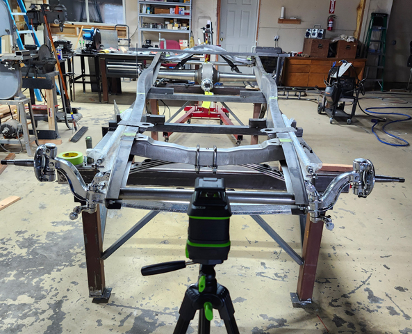
32 Ford Frame On A Build Platform |
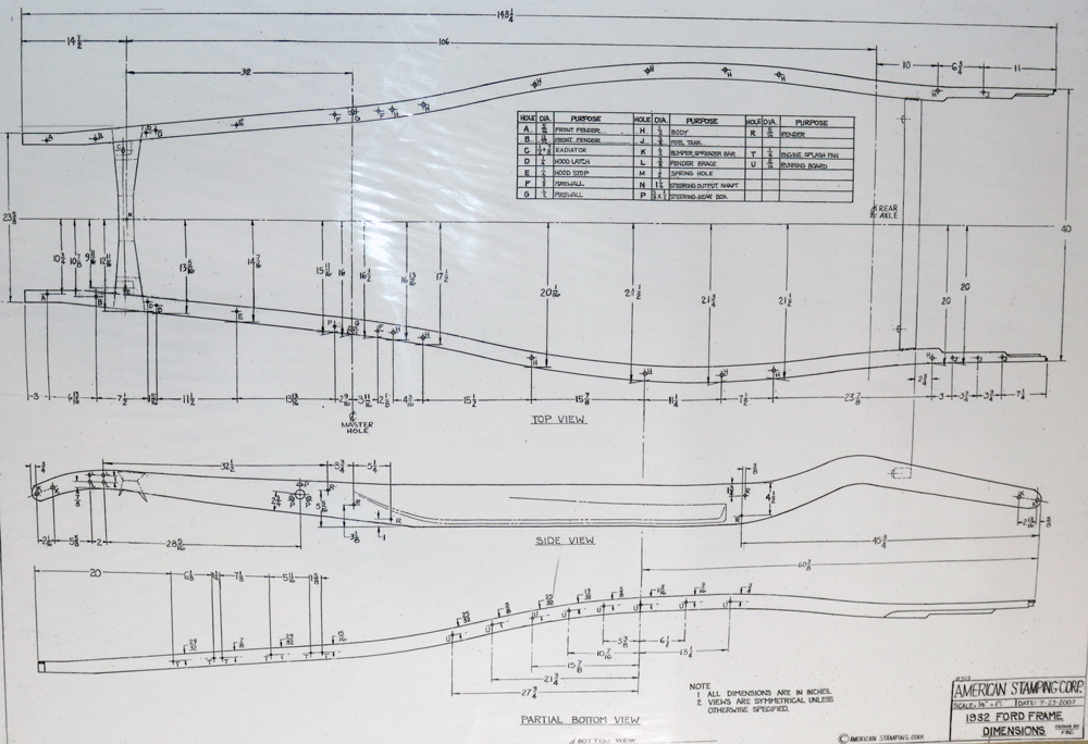
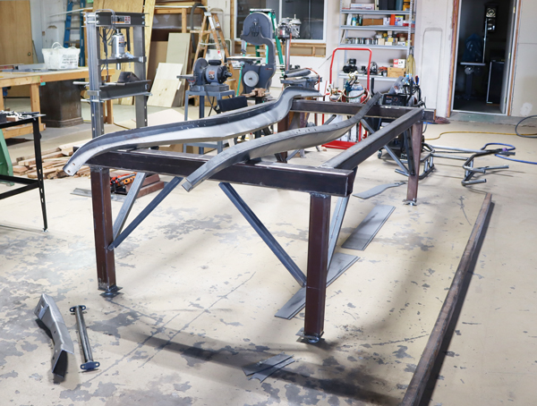
The chassis being the foundation of your hot rod it has to be square and level. I built a frame platform with two 4" x 4" x 3/16" sq. steel tube on cinder blocks. It worked good. Spreader bars for the front and rear will give you the proper width. When the spreaders are installed you will have a triangle that you can take a cross measurement for checking square. American Stamping makes 32 frames and has a blueprint of the original 32 Ford Frame. It is pictured above. According to the blueprint, the front outside measurement should be 23 5/8" and the rear outside measurement should be 40". Make sure you purchase the proper width spreader bars, or ship for proper width. There are many lengths offered - BEWARE! |
Fitting the boxing plates, I recommend you tack them in place and check the chassis for being square and level with the platform. When you permanently weld the plates in place do a little at a time so you do not heat the frame and distort it. (I learned this the hard way)
Boxing a frame without a solid frame table can be done but, but it is harder to keep everything square and level.
|
 |
 |
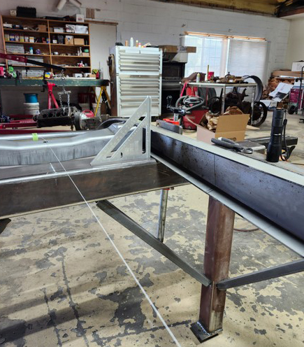
CHASSIS TABLE |
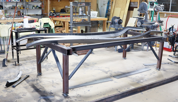
We built a Chassis table. We took the 4" x 4" x 3/16" box tubing, from our old setup, and welded on 3" x 3" x 3/16" box tubbing legs. We used two 8 foot x 3" x 3" x 3/16" box tubbing for our table stringers and added angle iron leg braces. A simple build with many benefits. Important to make sure your table is lever. I recommend that you use a laser. |
 |
 |
|||
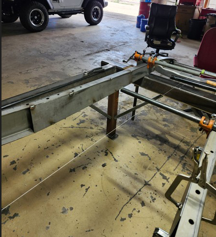
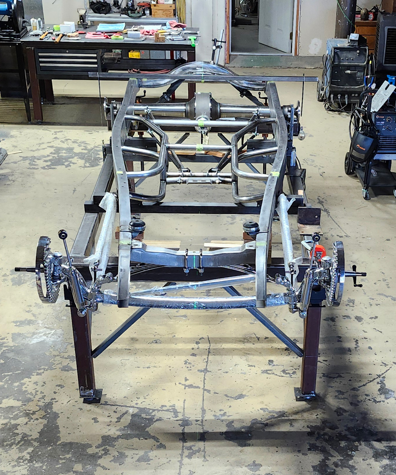
Setting Up Frame Rails On Chassis Table |
||||
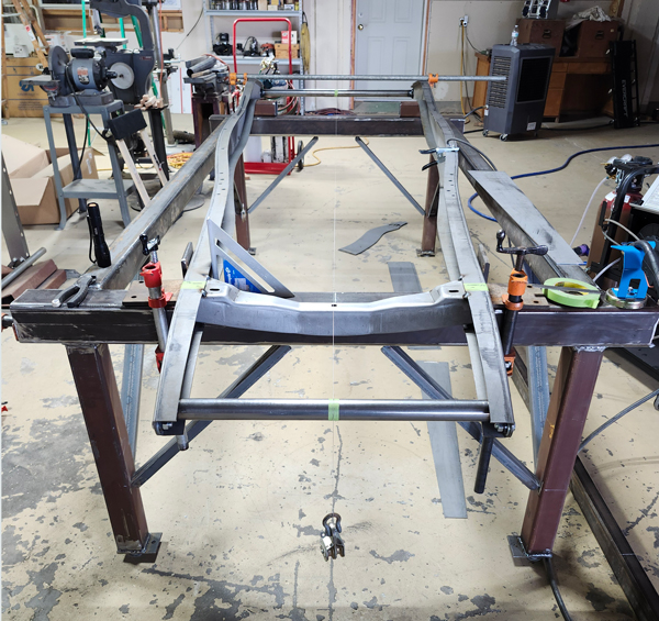
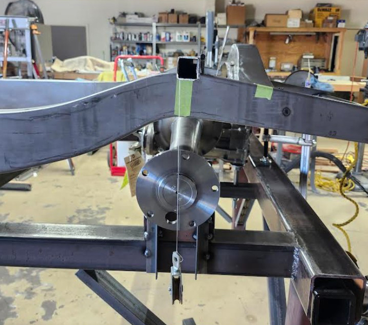
Install the spreader bars - front outside dimension 23 5/8" and rear is 40". If you start out with the proper dimension and keep everything straight and square your body will fit on the frame with mount holes lined up perfectly. We had some 3/8" x 4" angle that we clamped to the chassis table and frame rails. This made the rails at right angles to the table, we did the same at the rear. We then took the center of the rear spreader and the center of the front spreader and ran a string from the rear to the front. You now can take a cross measurement from the rear rail to the opposite front rail. Measure both opposite sides, they should be the same measurement. Clamp the frame securely to the table. you are now ready to start welding. Put the front cross member in place with the center hole center on the string. The center hole of the front cross member and the radiator mount holes will be the reference in placing all other components in building your chassis. IMPORTANT - Your need to check your rails for being square to the table as will a being square with cross measurement regularly. |
 |
Welding in Boxing Plates |
Fit your boxing plates, and clamp them in place. Tack them in placed. Keep checking the measurements provided on the Ford Blue print, if they get off, make an adjustment. When you get them all fitted then you can finish your welding. Weld in small areas at a time. If you weld to long in one spot you can distort the rails. Take your time. When you are finished you can grind off the excess weld and polish the frame rails. |
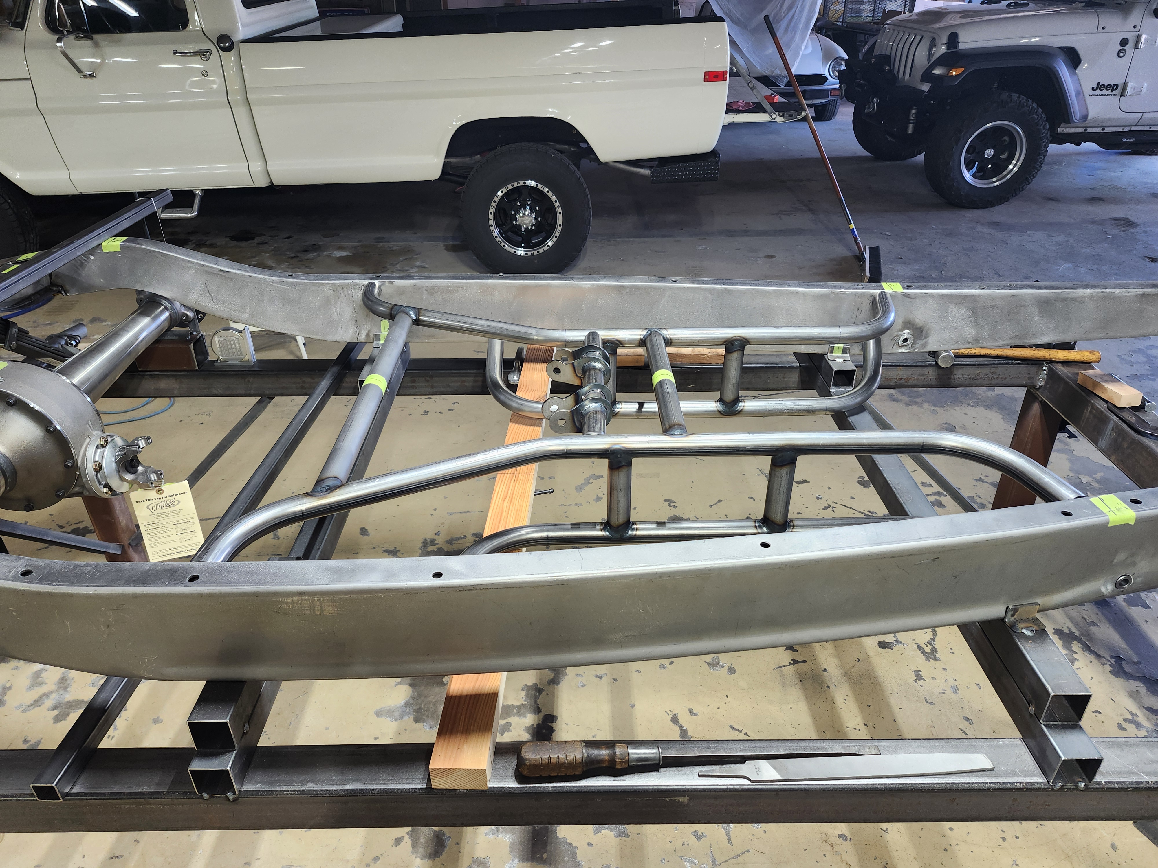
FITTING CHASSIS PARTS |
 |
 |
.jpg)
Click On Image For Larger View |
 |
 |
Click On Image For Larger View |
| Parts Used In This Frame Build All parts were purchased from Pete & Jakes 3095-C - Front End I Beam Axel (chrome) includes Hairpins & Radius Rods 2024 Cross member 3520 - Tubular Cross member with T5 Transmission Mount 3011B - Ladder Bar Kit 2025 -Rear Cross member 2058 - Rear Posie Spring 3070-C - Rear Shock Kit 5019 - Rear Spring Mounts |
More To Come |